Don't have an account? Join for free
-
-
All Categories
-
Construction
-
Marine
-
Subsea
-
Process Equipment
- View All Process Equipment
- Compressor
- Controls
- Diesel Generator
- Fire Suppression
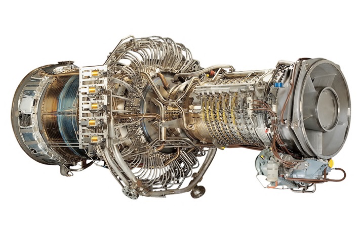
- Gas Turbine
- Motors
- Pressure Vessels
- Separators
- Heater Treater
- Heat Exchanger
- Coalescers
- Tanks
- Pumps
- Water Treatment
- Piping
- Structural
- Flanges
- Electrical
- Valves
- Instrumentation
- Bearings
- Measurement
- Meters
- Thermometers
-
Chemicals
- Communications
- IT
- Scaffolding
- HVAC
- Accommodations
- Light Masts
- Flare Stacks
- Pumpjacks
- Chokes
- Pigs
- Gas Detection
- Potable Water
- Fire Fighting
-
Renewable
- Hydraulics
- Steam Turbine
- LNG
- CNG
- RNG
- Biogas
- Hydrogen
- Nitrogen
- CCUS
- Piping
- Pipelines
- Personnel
- Gas Plant
- Oil Battery
- Alternative Energy
-
Transport
-
Workover
- View All Workover
-
Logging
-
Slickline
- Slickline Surface Equipment
- Slickline Basic Tools
- Slickline Standard Tools
- Slickline Baker Tools
- Slickline Remedial Equipment
- Slickline Special Tools
- Slickline Pulling Tools
- Slickline Camco Tools
- Slickline Petroline Tools
- Slickline Halliburton Tools
- Slickline Fishing Tools
- Swab Cups
- Lead Impression Block
- Slickline Swage Tool
- Slickline BOP
- Slickline Pressure Control Equipment
- Wireline Insert Valve
- Inflatable Packers
- Cement Retainers
- Slickline Surface Equipment
- Electric Line
-
Coiled Tubing
- Snubbing Unit
- Service Rig
- Flushby Unit
- Well Testing
-
Pumping
-
Perforating
-
Casing
-
Work Clothes
-
Tools
-
Waste Management
-
Industrial Cleaning
-
Completions
- View All Completions
- Packer Fluid
- Tubing Plugs
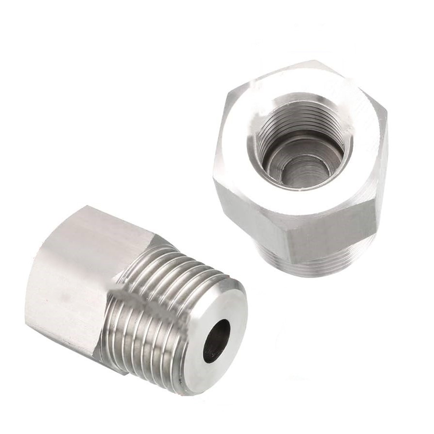
- Crossovers
- Nipple Profiles
- Sliding Side Doors
- Sliding Sleeve
- Side Pocket Mandrel
- Downhole Camera
- Fishing Tools
- X-mas Trees
- Wellheads
- Pup Joints
- Downhole Gauges
- Safety Valves
- SCSSV
- Artificial Lift
- Electric Submersible Pumps
- Gas Lift Valves
- Rod Pumps
- Beam Pumps
- Progressive Cavity Pumps
- Plunger Lift
- Tubing
- Packers
- Control Line
- Cross Coupling Protectors
- Slotted Liners
- Gravel Pack
- Perf Guns
- Sand Screens
- Multi Lateral Junctions
- Methanol
- Chemical Injection
- Wellhead Control Unit
- Air Compressors
- Pressure Gauges
- Hydraulic Control Unit
- Emergency Shutdowns
- Fire and Gas Detection
- Pressure Recorders
- Back Pressure Valves
- Tubing Hanger
-
Drilling
- View All Drilling
- Riser
- Blowout Preventer
- Accumulator
- Koomey Unit
- Rams
- Blind Rams
- Pipe Rams
- Shear Rams
- Variable Rams
- Annular
- TIW Valve
- Lubricator
- Top Drive
- Kelly Bushing
- Kelly Hose
- Slips
- Offices
- Piperack
- Drawworks
- Tongs
- Coring
-
Bits
- Mud Motors
- Iron Roughneck
- Monkeyboard
- Skidding System
- Under Reamer
- Lost Circulation Material
- LCM
- Landing Joints
- Drill Collars
-
Mud Mixer
- Casing Centralizers
- Pipe Dope
- Thread Protectors
- Hoses
- Chicksan
- Choke Manifold
- Heave Compensator
-
Open Hole Logging
- Cased Hole Logging
- Cuttings Handling
- Drilling Mud
- Elevators
-
Mining
-
All Categories
- Index Directory
- Onshore
- Offshore