Don't have an account? Join for free
Cart
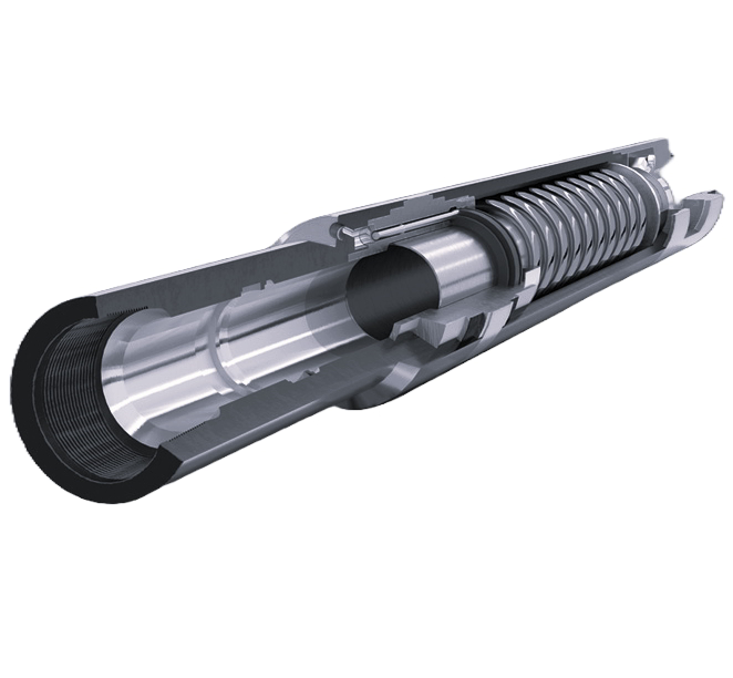
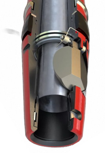
5 1/2" Mech-2 Double Grip Mechanical Set Packer for 20-23 PPF Casing
Ballycatter Mech-2 Double Grip Mechanical Packer
Available sizes: 5”, 5 1/2”, 6 5/8”, 7”, 9 5/8”, and 10 3/4”
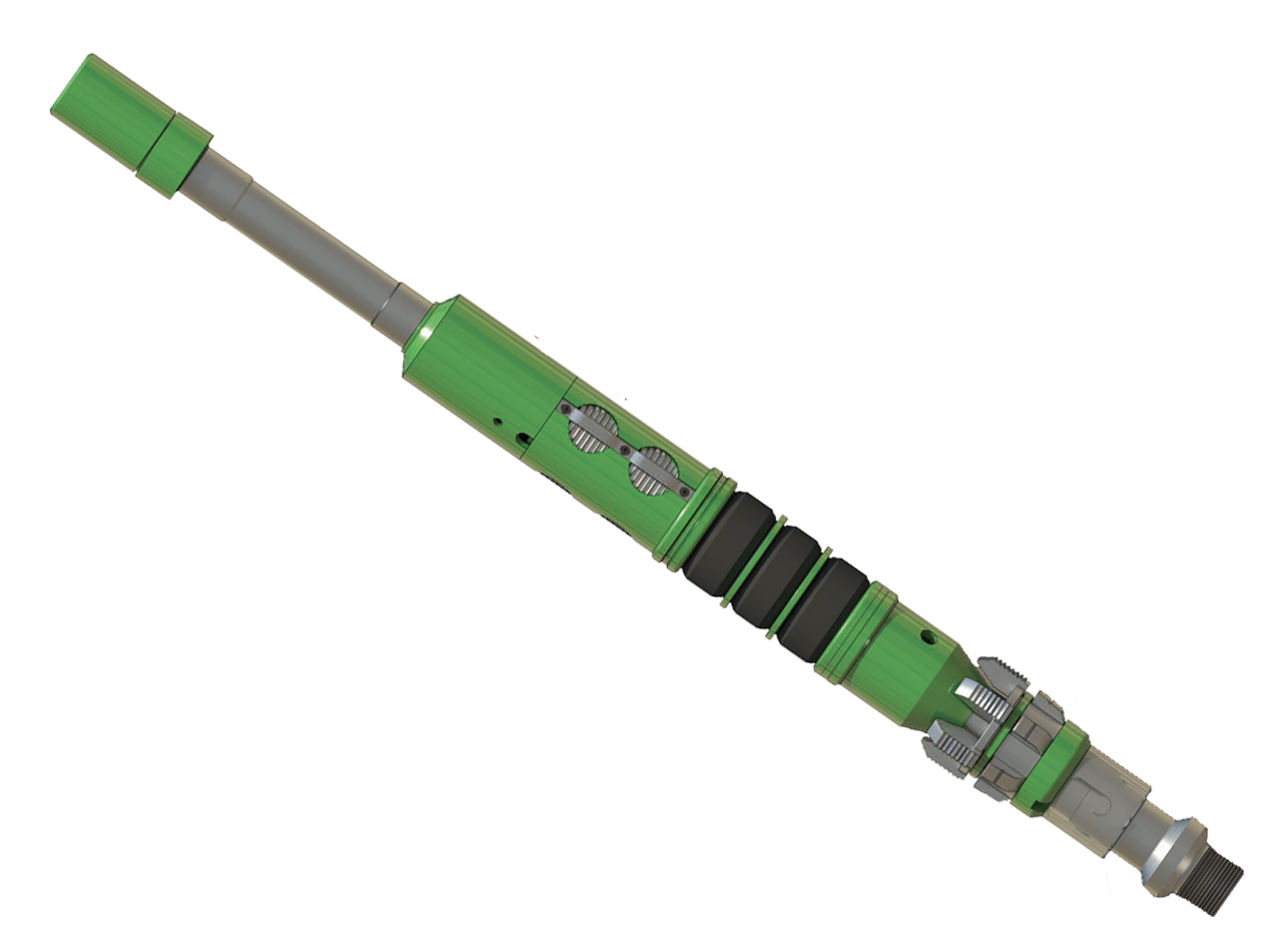
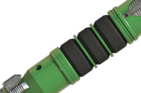
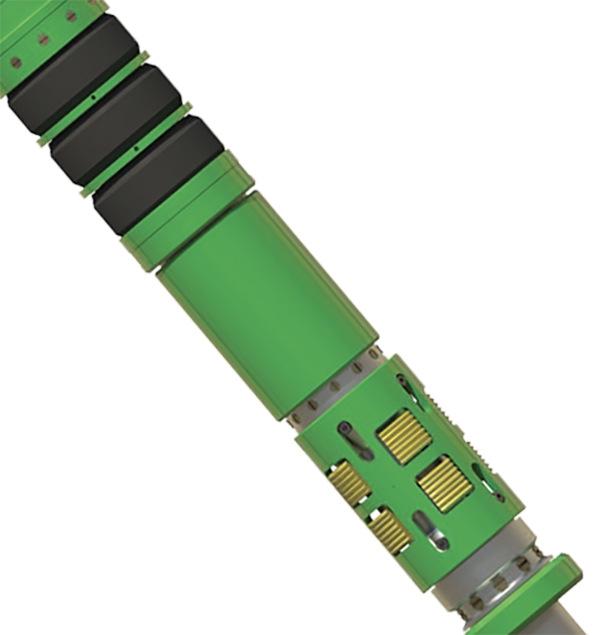
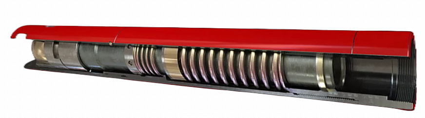
The Ballycatter Mech-2 is a retrievable, compression-set double-grip mechanical packer designed for applications where pressure differentials from below are anticipated, such as combined stimulation and production operations. Featuring opposing slips above and below the packing element, the Mech-2 ensures secure bi-directional anchoring within the casing under varying well conditions.
The tool incorporates a built-in hydraulic hold-down system located beneath the face-seal bypass valve, enabling it to resist upward forces during stimulation treatments. A unique “Differential Lock” mechanism utilizes pressure from below the packer to actuate a balance sleeve, generating additional downward force that maintains bypass valve integrity and ensures a reliable seal.
The Mech-2 is mechanically set using a long-stroke mandrel and a J-slot mechanism. Once positioned, right-hand rotation and applied set-down weight close the bypass valve, engage both slip sets, and compress the sealing elements. The formation below the packer is then fully isolated and accessible only through the tubing. To retrieve, the tubing is raised the full packer length, automatically re-engaging the J-slot and reopening the bypass for pressure equalization and circulation.
With its dual-grip design, hydraulic hold-down, and controlled setting and release process, the Mech-2 offers a robust and dependable solution for demanding applications requiring secure annular isolation and enhanced downhole stability.
View Details
7" Mech-2 Double Grip Mechanical Set Packer for 20-26 PPF Casing
Ballycatter Mech-2 Double Grip Mechanical Packer
Available sizes: 5”, 5 1/2”, 6 5/8”, 7”, 9 5/8”, and 10 3/4”
The Ballycatter Mech-2 is a retrievable, compression-set double-grip mechanical packer designed for applications where pressure differentials from below are anticipated, such as combined stimulation and production operations. Featuring opposing slips above and below the packing element, the Mech-2 ensures secure bi-directional anchoring within the casing under varying well conditions.
The tool incorporates a built-in hydraulic hold-down system located beneath the face-seal bypass valve, enabling it to resist upward forces during stimulation treatments. A unique “Differential Lock” mechanism utilizes pressure from below the packer to actuate a balance sleeve, generating additional downward force that maintains bypass valve integrity and ensures a reliable seal.
The Mech-2 is mechanically set using a long-stroke mandrel and a J-slot mechanism. Once positioned, right-hand rotation and applied set-down weight close the bypass valve, engage both slip sets, and compress the sealing elements. The formation below the packer is then fully isolated and accessible only through the tubing. To retrieve, the tubing is raised the full packer length, automatically re-engaging the J-slot and reopening the bypass for pressure equalization and circulation.
With its dual-grip design, hydraulic hold-down, and controlled setting and release process, the Mech-2 offers a robust and dependable solution for demanding applications requiring secure annular isolation and enhanced downhole stability.
View Details
Electric Submersible Pump ESP Packer – 7" – 3,500 PSI
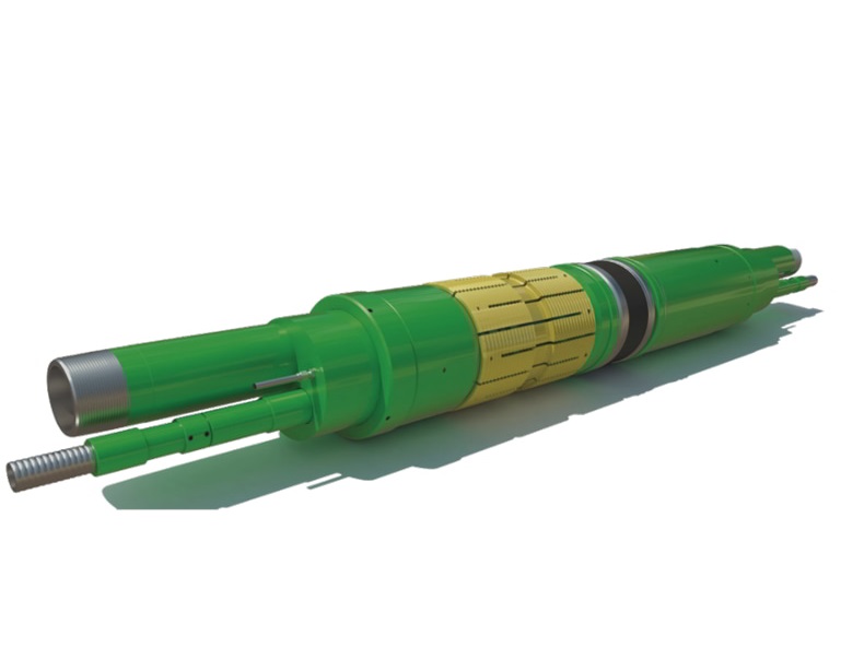
The 7" ESP Packer is a single-mandrel, dual-bore, hydraulic-set production packer set in place using hydraulic pressure applied through the tubing. The dual-bore configuration includes a pass-through section that allows the electric cable to reach the ESP pump below the packer while maintaining isolation between the tubing and the annulus, enabling reliable deployment and operation of the ESP system for artificial lift in oil and gas wells.
The packer has bi-directional, case-carburized barrel slips that anchor it securely against well pressures from both above and below, preventing movement during operation. It can be retrieved with a straight upward pull on the tubing string and is available in both straight-pull and cut-to-release configurations to suit different well conditions.
The packer has a nominal size of 7" and fits 7" casing weighing 26–32 PPF or 7-5/8" casing weighing 55.3 PPF. The outer diameter is 5.970", and the main bore inner diameter is 2.992". The assembly allows up to five feed-through lines for electric cables or injection lines, and the total length is 125".
The body is made from L80 material with HNBR elastomer seals, rated for pressures up to 3,500 PSI and temperatures from 70°F to 300°F. Connections include a 3-1/2", 9.2 PPF VAM TOP box at the top and a 3-1/2", 9.2 PPF VAM TOP pin at the bottom. The release weight is 68,800 lbs. The packer meets API Validation Grade V3 and Quality Level QL1 standards, providing reliable performance under standard service conditions.
These attributes make the ESP packer reliable for high-load applications, adaptable to various completion designs, and efficient in facilitating ESP deployment in oil and gas wells.
View Details
Safety Valve for Water Injectors 5.71 inch
The WI retrievable injection valve is a high-performance, high-flow rate injection valve. High throughput is achieved by a unique valve configuration that minimizes turbulent and potentially erosive flow. Operation is not dependent on a specific flow rate, pressure, or setting depth, thus negating the need for adjustment over time. The valve incorporates a metal-to-metal valve and seat energized by the combination of an integral spring and well pressure acting from below. The WI injection valve can be deployed on a wireline lock or through-tubing pack-off device, providing flexibility not available with alternative injection valve systems. As a result of the simple design with fewer parts, redress and repair costs are considerably lower than those for other injection valve systems. Applications The WI injection valve is primarily used in water injection applications as an alternative to conventional tubing or wireline-set safety valves. The valve is also commonly used as a retrofit solution in water injectors in which a tubing to annulus leak has occurred. The valve can be deployed below the leak point to eliminate uncontrolled annulus pressure increases when the injection stops. Features » Compatible with all known lock systems » Dedicated designs to suit Halliburton EB0 intervention packers » Enhanced internal flow profile » Simple design and construction » Flow-loop testing performed to establish pressure drop versus pump rate *information referenced from supplier catalog. View Details
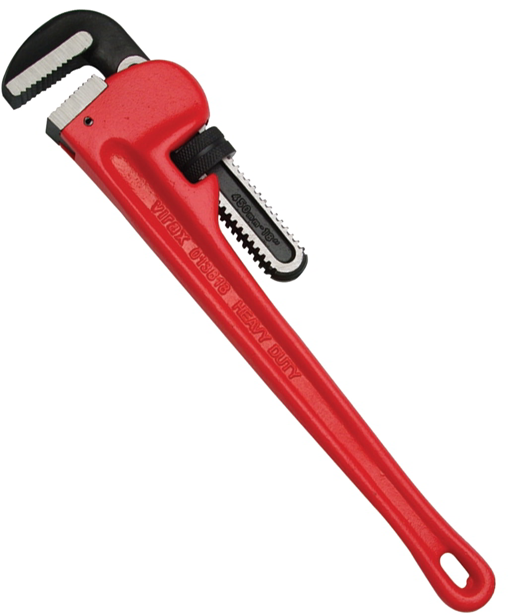
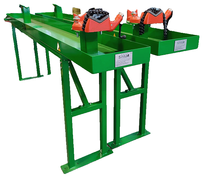
Well Servicing Pipe Wrenches for torquing tubulars and downhole tools
The adjustable pipe, or Stillson, wrench is used to hold or turn pipes or circular bars. This wrench has serrated jaws, one of which is pivoted on the handle to create a strong gripping action on the work. When torquing with a pipe wrench remember the tool push phrase - 24 tight and 48 loose! View Details
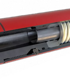
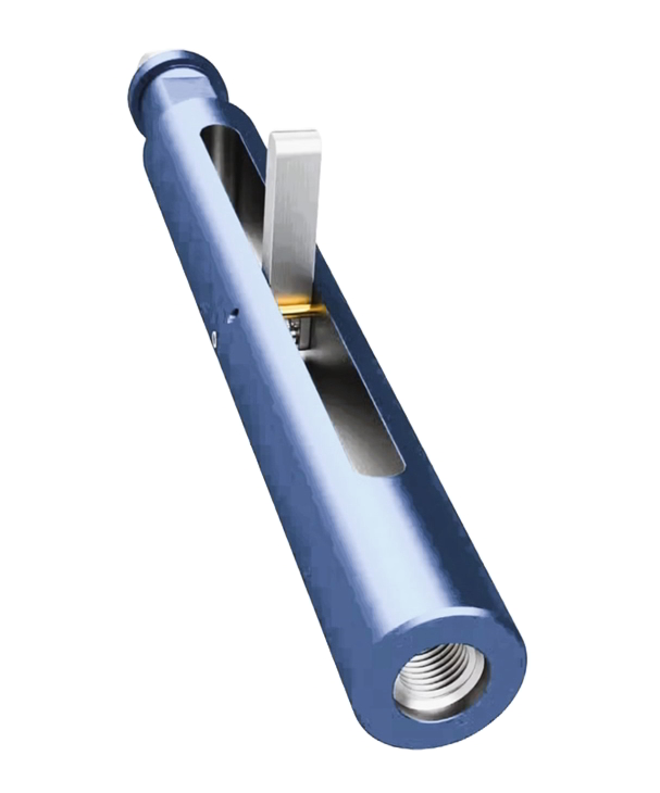
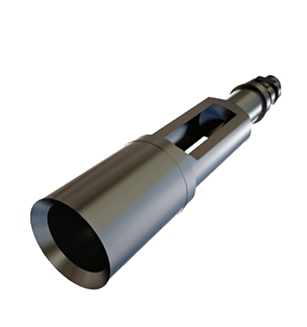
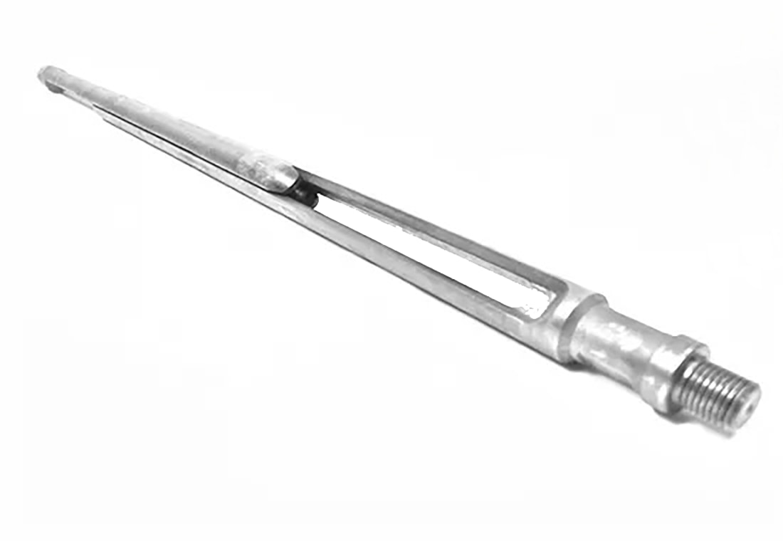
In oil and gas well operations, the 2 ½” Tubing End Locator plays a critical role in confirming the exact depth at which production tubing terminates within the wellbore. Accurately identifying the tubing endpoint is essential during various well intervention activities, including maintenance, workovers, and the installation or retrieval of downhole tools and equipment.
During operations such as setting packers, deploying plugs, running logging tools, or performing fishing jobs to recover stuck equipment, precise knowledge of tubing length ensures that tools are positioned correctly. This prevents accidental over-pumping or tool deployment beyond the tubing into the open hole section of the well, where damage to equipment or tool loss can occur.
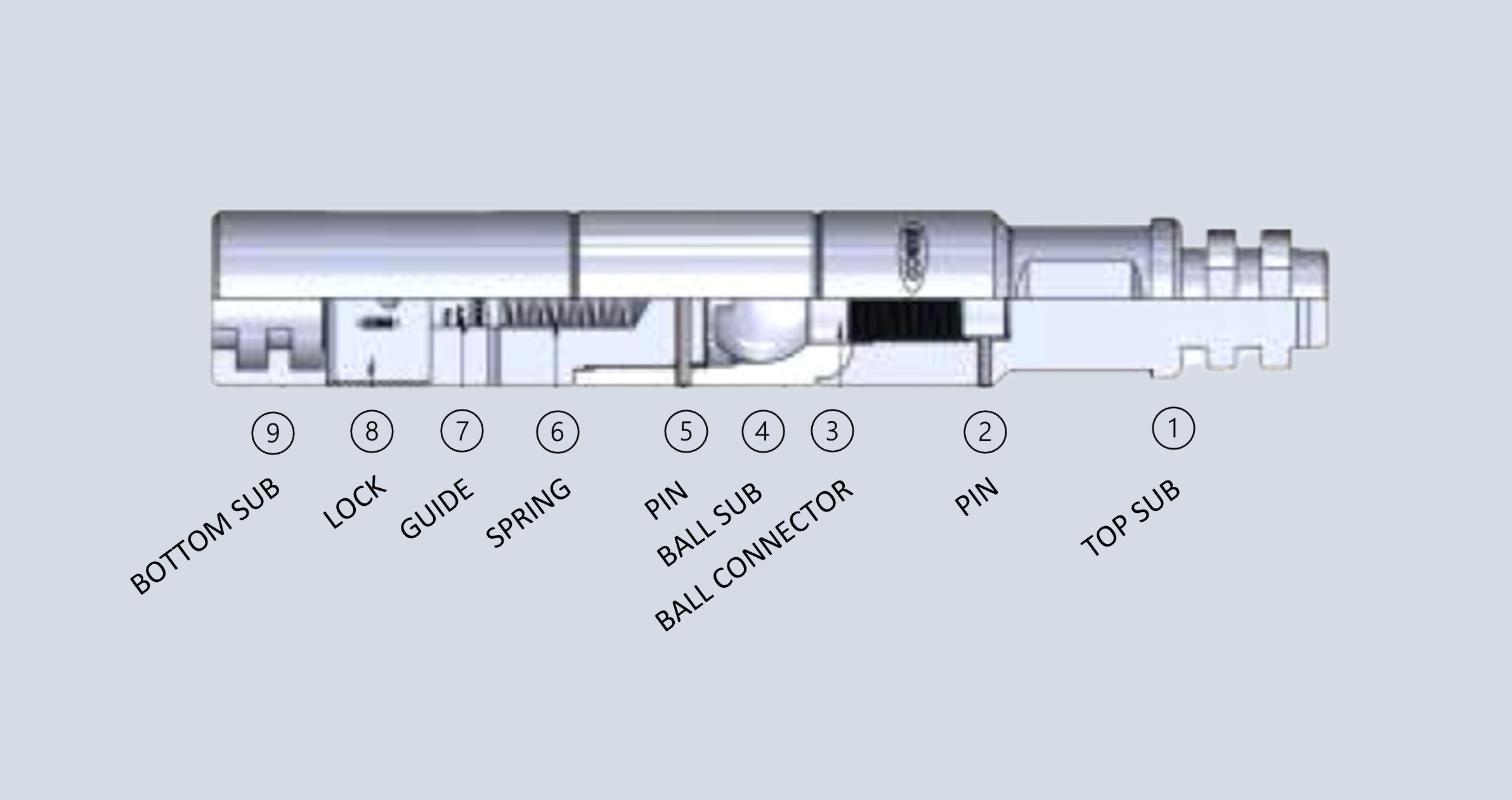
The 2 ½” Tubing End Locator is designed specifically to fit tubing with an outer diameter of approximately 2 ½ inches. It features a compact maximum outside diameter of around 1.750 inches, allowing it to pass easily within the tubing without causing obstruction. The tool employs a spring-loaded finger mechanism that activates mechanically upon reaching the tubing bottom. This signal does not rely on electronic sensors or depth measurement devices, making the tool highly reliable even in harsh downhole environments where electronics may be compromised by pressure, temperature, or fluid conditions.
Standardized threaded connections on the tool—typically a 15/16 - 10 UN pin on the top and a 1 - 11 1/2 NPT box on the bottom—enable it to be seamlessly integrated into a wide range of intervention toolstrings. These common connection types ensure compatibility with existing downhole equipment and facilitate quick assembly and deployment.
Manufactured from high-strength alloy steel or similar materials, the tubing end locator is built to withstand typical downhole conditions, including high pressure, elevated temperatures, and corrosive fluids commonly found in oil and gas wells. Its purely mechanical design minimizes maintenance requirements and reduces the risk of failure compared to electronic alternatives.
This tool is particularly valuable in wells where tubing length may have changed due to wear, repairs, or previous interventions, offering an essential measure of control and confidence in complex well environments.
View Details
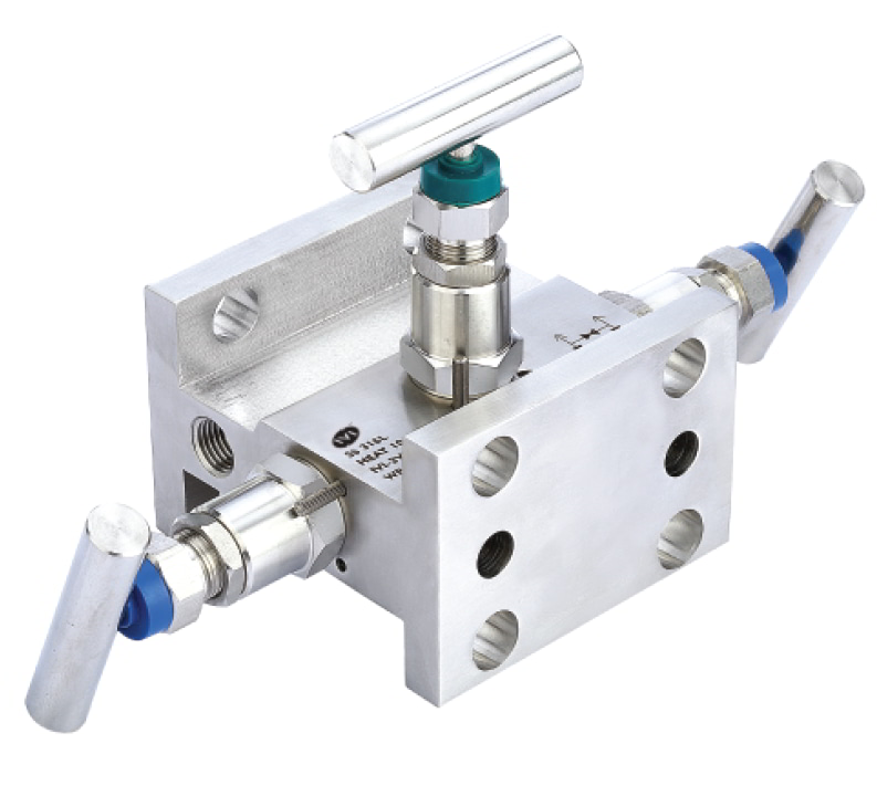
The H Type 3 Valve Manifold – Flange to Flange is designed for connecting impulse lines and differential pressure transmitters in oil and gas and industrial process applications. It consists of two block valves, one equalizer valve, and two ¼” Female NPT vent/test connections, providing accurate isolation, calibration, and maintenance of instrumentation.
The manifold is rated for a standard working pressure of 6000 PSI, with maximum ratings up to 10000 PSI available on request. Temperature ratings range from -50°C to 230°C, with 500°C possible using graphite seals. The body features a metal-to-metal seal for high pressure and temperature applications, eliminating the need for O-ring seals, and materials can be supplied according to NACE MR 01 75 standards.
Each valve is 100% factory tested per international pressure standards, including pneumatic testing with nitrogen at 1000 PSI for seat and packing leakage, with a maximum allowable leak rate of 0.1 sec/min. Stems have back seats, rolled threads, and self-centering non-rotating tips for consistent, leak-free operation. The H Type design allows reliable, safe, and precise operation in high-pressure, high-temperature process environments.
View Details
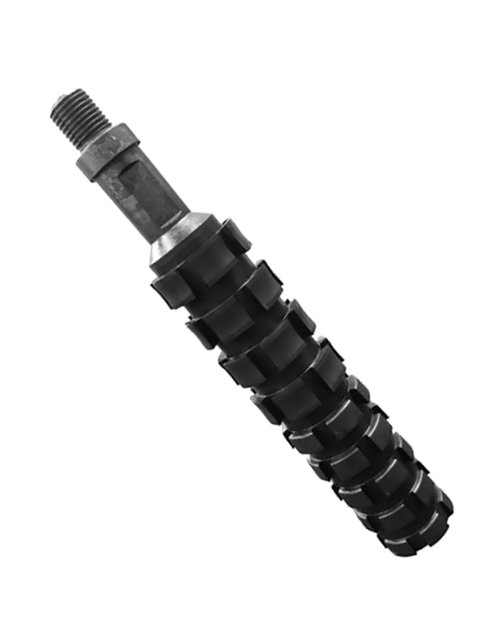
The 3” Tubing End Locator is a mechanical downhole tool used to identify the precise end of a 3-inch production tubing string during well intervention operations. It provides a clear physical indication when the tool reaches the bottom of the tubing, helping to ensure accurate placement of equipment inside the well.
Designed specifically for tubing with a 3-inch outer diameter, the tool features a maximum outside diameter of 2.500 inches. This sizing ensures smooth movement within the tubing while maintaining close contact, allowing the tool to operate effectively without the risk of sticking or misalignment. At the core of the design is a spring-loaded finger mechanism that extends outward when the tubing end is reached. This mechanical movement is transmitted to the surface as a tactile response, signaling that the tubing bottom has been contacted.
The tool includes standard threaded connections—such as a 15/16 - 10 UN pin on the top and a 1 - 11 ½ NPT box on the bottom—which makes it compatible with a variety of toolstring configurations. It can be easily incorporated into slickline, wireline, or coiled tubing assemblies without the need for special adapters.
Constructed from durable, corrosion-resistant materials, the tubing end locator is built to perform reliably in downhole environments that involve high pressure, elevated temperature, and exposure to fluids. Its fully mechanical operation ensures a high level of dependability and minimizes the need for maintenance, especially in conditions where electronic systems may not be suitable.
The 3” Tubing End Locator is a practical solution for confirming tubing depth when preparing the well for further intervention.
View Details
Maui ROV, Heavy Inspection Class ROV
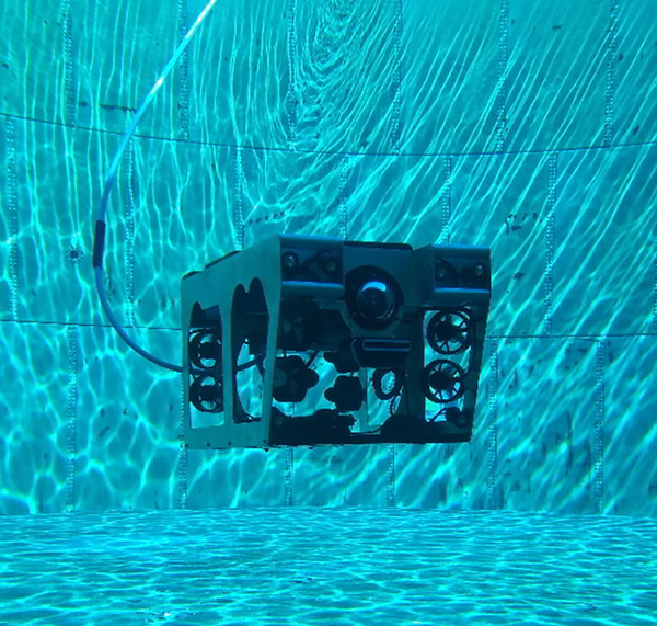
Designed for the Extraordinary - Meet Maui ROV Are you ready to take your subsea operations to new heights? Introducing Maui ROV, the ultimate subsea solution designed with large payloads in mind. With its cutting-edge vectored thruster layout, professional Aluminum frame, and remarkable payload capacity, the Maui ROV stands out as a true game-changer in the industry. Mastering the Depths The Maui ROV is built to conquer challenging dives with ease, making it the ideal choice for survey work or heavy lifting tasks. Its impressive capabilities stem from the ingenious combination of design elements that result in unparalleled performance. Powerful Features for Unmatched Performance 1. Industrial Flight Computer and Linux User Interface: The Maui ROV features an industrial flight computer and user-friendly Linux interface, ensuring seamless control and precise maneuverability. 2. Topside Integrated Console: Equipped with a 22-inch sunlight-readable monitor and a hand controller, the Topside Integrated Console eliminates the need for additional equipment, streamlining your operations. 3. 6-Axis Stability and Fully Stabilized Mode: The Maui's ROV flight computer supports 6-axis stability, providing unmatched control and stability during underwater missions. 4. Exceptional Payload Space: Utilizing smaller diameter thrusters stacked vertically, the Maui ROV boasts exceptional payload space, enabling it to carry various instruments such as the Coda Octopus 3D Sonar, INS, Multibeam Profilers, or Sub Bottom Profilers. Experience the Specifications of Excellence Take a closer look at the impressive specifications that make the Maui ROV an indispensable asset for your subsea ventures: • Depth Rating: 400m • Dimensions: 725x465x425mm (LWH) • Weight in Air: 31.2kg • Payload Capacity (Fresh Water): 9.3kg • Payload Area: 610mm x 457mm • Thrusters: 8 lateral (45deg), 6 vertical • Ballard Pull: 27kg lateral, 28kg vertical • Top Speed: 3 knots • Video: 1080 HD IP camera with tilt • Aux Video: 2 HD camera inputs • Lights: 8x 1,500 Lumen each • Connectivity: 1x Ethernet, 4x Serial • Aux Power: 5/12/24/48VDC regulated Topside Integrated Console Specifications: • Output Voltage: 400VDC, 3kW • Input Voltage: 240VAC, 15A maximum • Monitor: 22in HD sunlight-readable • Case: Wheeled, 610x420x260mm, 24kg • Fully Isolated Output with LIM • Intel i5 PC with Windows 10 Installed • Aux HDMI Monitor Output Tether Specifications: • Breaking Strength: 250kg • Diameter: 9.1mm • Length: Up to 500m • Neutral in Fresh Water Explore the Depths with Maui ROV Unleash the power of heavy payloads and challenging dives with the Maui ROV. Let our state-of-the-art technology redefine your subsea operations and elevate your success. View Details
Subsurface Direct Controlled Safety Valve 4.26 inch
The WI retrievable injection valve is a high-performance, high-flow rate injection valve. High throughput is achieved by a unique valve configuration that minimizes turbulent and potentially erosive flow. Operation is not dependent on a specific flow rate, pressure, or setting depth, thus negating the need for adjustment over time. The valve incorporates a metal-to-metal valve and seat energized by the combination of an integral spring and well pressure acting from below. The WI injection valve can be deployed on a wireline lock or through-tubing pack-off device, providing flexibility not available with alternative injection valve systems. As a result of the simple design with fewer parts, redress and repair costs are considerably lower than those for other injection valve systems. Applications The WI injection valve is primarily used in water injection applications as an alternative to conventional tubing or wireline-set safety valves. The valve is also commonly used as a retrofit solution in water injectors in which a tubing to annulus leak has occurred. The valve can be deployed below the leak point to eliminate uncontrolled annulus pressure increases when the injection stops. Features » Compatible with all known lock systems » Dedicated designs to suit Halliburton EB0 intervention packers » Enhanced internal flow profile » Simple design and construction » Flow-loop testing performed to establish pressure drop versus pump rate *information referenced from supplier catalog. View Details
MS-201EC Extraction Condensing Steam Turbine
Elevate Your Energy Solutions with the Kessels MS-201 EC Extraction Condensing Steam Turbine: Efficiency Perfected In the dynamic world of the oil and gas industry, precision, performance, and sustainability are non-negotiable. Kessels Steam Turbines is proud to introduce the MS-201 EC Extraction Condensing Steam Turbine, a technological marvel that sets new standards in steam turbine excellence. Mastering Extraction Condensing Turbines Extraction condensing turbines are the lifeline of industries requiring a constant pressure steam flow for diverse processes. The MS-201 EC shares structural characteristics with condensing turbines, making it the ideal choice when you need a reliable source of constant pressure steam for your operations. Efficiency at Its Pinnacle What distinguishes the MS-201 EC is its remarkable capability to inject low-pressure steam from the second admission valve chest. This ingenious feature optimizes the utilization of available plant resources to meet power demands, making our turbine an indispensable asset in co-generation scenarios. Steady Power, Unwavering Performance In co-generation settings, where maintaining a consistent power supply despite fluctuations in process steam demands is paramount, the MS-201 EC shines. This turbine ensures your power generation remains steady, providing a rock-solid foundation for your operations. Ultimate Versatility At Kessels, we understand that each industry has unique needs. In some cases, you may require both bleed and controlled extraction steams from the condensing turbine. Our MS-201 EC is designed to meet these demands, offering the flexibility of a bleed cum extraction condensing turbine. Why Choose Kessels? Choosing Kessels Steam Turbines isn't just a business decision; it's a commitment to excellence, innovation, and reliability. Our MS-201 EC Extraction Condensing Steam Turbine embodies these principles, offering you: Unmatched Efficiency: Harness low-pressure steam resources efficiently, reducing energy waste and maximizing productivity. Reliability Beyond Question: Crafted with precision and subjected to rigorous testing, our turbine ensures uninterrupted operations, even in the most demanding industrial environments. Consistent Power Supply: Experience uninterrupted power generation, regardless of variations in process steam demands, ensuring your operations run seamlessly. Exceptional Versatility: Adapt effortlessly to your unique requirements, whether you need bleed or controlled extraction steams, with the confidence that Kessels' expertise provides. Expert Support: Our team of specialists is at your service, ready to assist with installation, maintenance, and troubleshooting. Empower Your Future with Kessels In the fiercely competitive landscape of the oil and gas industry, every advantage counts. Step into a future of efficiency, reliability, and sustainability with the Kessels MS-201 EC Extraction Condensing Steam Turbine. Contact us today to discover how our turbine can revolutionize your operations and lead you toward unprecedented success. Kessels Steam Turbines – Powering Progress, Powering You. View Details
Wireless Communication Tower Construction
Soaring Above Communication Challenges: Nulux Network Solutions Pioneers in Wireless Tower Construction for the Oil and Gas Industry Exploration, extraction, and operational activities in the oil and gas industry are intrinsically bound to the formidable environments - remote locations, vast distances, and oftentimes, challenging terrains. Navigating through these physical barriers to establish a stable, secure, and scalable communication network necessitates innovative and robust solutions. This is where Nulux Network Solutions ascends, bridging the communication divide with unparalleled expertise in Wireless Communication Tower Construction. Pillars of Communication: Why Tower Construction Matters The landscape of the oil and gas sector demands the creation of a network that is not only extensive but also exceptionally reliable. Communication towers become the veritable backbone, linking disparate operations, ensuring data flow, and maintaining a coherence that is vital for smooth functionalities and decision-making processes. Constructing these towers, especially in the arduous terrains that characterize the oil and gas industry, requires a blend of engineering expertise, practical experience, and an acute understanding of wireless communication nuances. Nulux’s Distinction: A Synthesis of Experience and Innovation With an illustrious history in designing and implementing an array of wireless systems and infrastructures, Nulux has emerged as a leader in wireless tower construction and rigging, ensuring that the tapestry of communication across your operations, be it P2P or Multipoint networks, remains uninterrupted and secure. Adaptivity and Scalability: As your operations evolve, so does your communication network. Our towers are constructed with a forward-looking approach, ensuring they are capable of adapting to technological advancements and scalable to accommodate your expanding operational horizons. Reliability in Rigorous Environments: Our construction protocols and strategies are molded by our extensive experience in various terrains and environments, ensuring that the towers stand resilient in the face of geographical and meteorological challenges. A Mesh of Connectivity: Whether linking the executive decisions from central offices to the far-reaching extraction sites or facilitating data-driven operations across the entire network, our towers ensure that every node remains perpetually connected. Navigating Through P2P and Multipoint Networks Understanding and integrating varied network configurations such as P2P and Multipoint networks into our tower construction strategy, we ensure that the specific communicational and operational prerequisites of your business are met. End-to-End P2P Solutions: For secure, dedicated, and high-speed communication between two points, our P2P network solutions, enabled by strategically positioned towers, ensure that your data travels securely and swiftly. Expansive Multipoint Configurations: When the operational framework demands centralized communication with multiple nodes, our towers facilitate a sturdy and coherent multipoint communication network. Your Partner in Progress: Nulux Network Solutions As we stride into the future, where the fusion of technology and operations will become even more intrinsic, Nulux stands as your partner, ensuring that the wireless communication networks powering your operations are not just contemporaneous but also future-ready. Connect with us, and let’s architect a communication network that empowers, enhances, and ensures the seamless functionality of your operations in the oil and gas industry, traversing through the present and into the future. View Details
MS-42 EB Multistage Steam Turbine
Unleash Power and Precision with the Kessels MS-42 EB Multistage Steam Turbine: Your Ultimate Back-Pressure Solution In the high-stakes world of the oil and gas industry, precision and performance are non-negotiable. That's why, at Kessels Steam Turbines, we're proud to introduce our cutting-edge MS-42 EB Multistage Steam Turbine – a powerhouse engineered to redefine excellence in back-pressure turbine technology. Mastering Back-Pressure Turbines Back pressure turbines have been the workhorses of industrial steam applications for decades, and our MS-42 EB takes their capabilities to new heights. Whether it's single-stage or multi-stage options, these turbines serve as the critical bridge between the boiler unit and the process steam header, revolutionizing steam utilization and power generation. Efficiency Redefined Our MS-42 EB Multistage Steam Turbine boasts the hallmark of back pressure turbines: their straight-back pressure nature. This design ensures the efficient harnessing of exhaust steam, meeting process demands with unparalleled precision. Every ounce of electrical power generated is consumed as per the process steam demand, offering unmatched efficiency. Applications Beyond Boundaries At Kessels, we understand that diverse industries have unique demands. That's why our MS-42 EB Multistage Steam Turbine excels in a wide range of applications: Drive Applications: Embrace the power of our turbine in oil and gas operations, sugar mills, sugar fibrizor systems, shredder drives, pump drives, and more. Wherever drive power is needed, Kessels delivers. Power Generation Applications: Elevate your sustainability game by using our turbine to generate electricity, powering generators with clean and efficient steam energy. Bleed Back-Pressure Steam Turbines Our commitment to versatility is evident in the design of the MS-42 EB. With built-in bleed points, uncontrolled extraction vents enable steam extraction within a medium pressure range. This feature proves invaluable in situations where bleeding steam is required at low volume steam demands and when there's a high tolerance for pressure variations. Kessels turbines seamlessly blend the best of both bleed and back-pressure mechanisms. Extraction Back-Pressure Steam Turbines When your process steam demand volume is substantial, and you can't compromise on pressure variations, our steam turbines with controlled extraction vents come to the rescue. These turbines operate under intermediate pressure levels, ensuring a steady and reliable steam supply that your operations can depend on. Why Choose Kessels? Choosing Kessels Steam Turbines means choosing a legacy of excellence, innovation, and reliability. Our MS-42 EB Multistage Steam Turbine is the embodiment of these principles, offering you: Unmatched Efficiency: Maximize steam utilization and minimize wastage with our precision-engineered turbine. Reliability Redefined: Rigorously tested and built with unwavering precision, the MS-42 EB ensures your operations run seamlessly. Unparalleled Versatility: Adapt to changing needs effortlessly, whether it's drive applications or eco-friendly power generation. Sustainability at Its Core: Harness the power of steam for electricity generation, reducing your carbon footprint and contributing to a greener future. Expert Support: Our team of specialists is always at your service, ready to assist with installation, maintenance, and troubleshooting. Empower Your Future with Kessels In the fiercely competitive oil and gas industry, every advantage matters. Step into a future of efficiency, reliability, and sustainability with the Kessels MS-42 EB Multistage Steam Turbine. Contact us today to discover how our turbine can revolutionize your operations and lead you towards a future of success. Kessels Steam Turbines – Powering Progress, Powering You. View Details
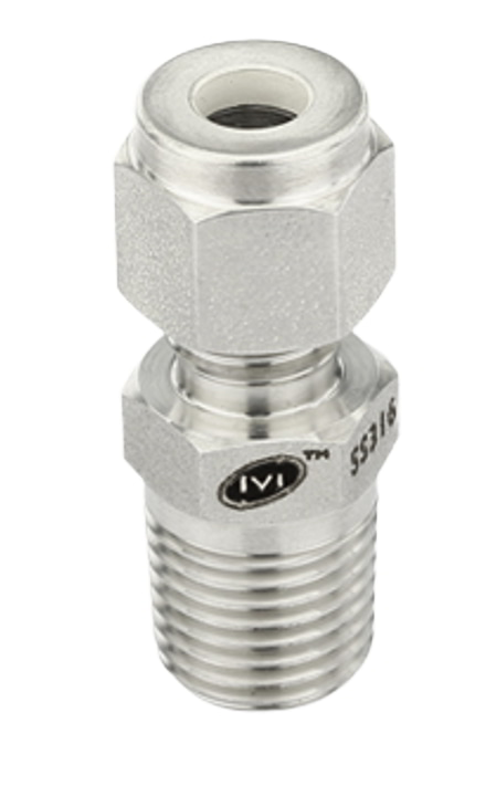
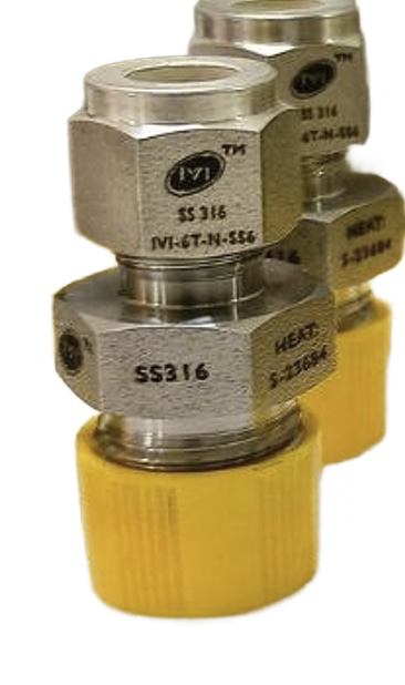
The Tube Fittings Male Connector with ISO Parallel Thread is designed to join tubing to parallel-threaded ports in high-pressure systems. This fitting ensures a tight, leak-resistant seal that maintains system integrity under pressures up to 6000 PSI, making it suitable for demanding oil and gas applications.
Constructed from high-quality materials, the fitting is manufactured to precise tolerances to ensure proper ferrule deformation and consistent performance. The parallel thread design allows for a straightforward installation and secure connection without excessive torque, reducing the risk of thread damage or galling.
These fittings are used extensively in pipelines, instrumentation, and process systems where a reliable and durable connection is required. The male connector configuration allows it to mate with female threaded components, providing versatility in system design. The robust design also ensures excellent performance under vibration, temperature changes, and fluctuating pressures.
Overall, this fitting combines technical reliability with ease of use, making it suitable for both engineering and operational personnel who require dependable tubing connections in oil and gas environments.
View Details
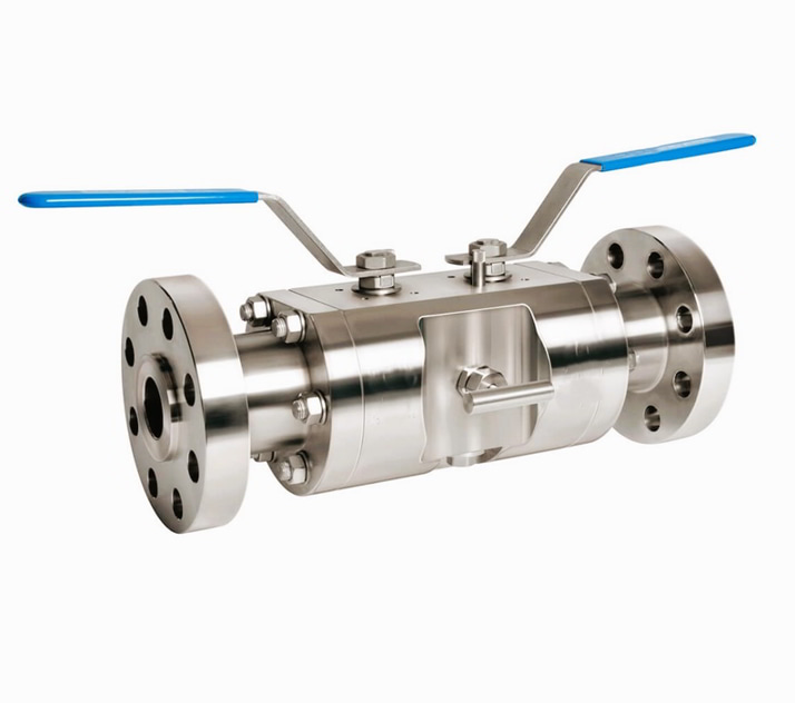
The Double Block & Bleed Valve Flange x Flange 3/4” (DN 20) with Ball isolation and Needle drain provides dual isolation in oil and gas piping systems. The first ball isolates upstream flow while the second ball isolates downstream flow. The needle drain vents trapped pressure between the two isolation points, making it suitable for instrument or gauge isolation, chemical injection, or sampling in operations where maintenance or measurement is required without interrupting the main process.
This specific 3/4” (DN 20) valve is rated for Class 150 service. It has a flange diameter of 100 mm, a bore of 69.9 mm, a flange thickness of 15.9 mm, and uses four bolts of 1/2” size. The face-to-face length is 203 mm. It is manufactured from materials compatible with oil and gas environments and meets ASME B16.34, API 6D, and ISO 17292 standards for pressure-temperature performance and reliability.
View Details
9 5/8" HP-6 Hydraulic Set High Angle Production Packer for 40-47 PPF Casing
Ballycatter HP-6 High Angle Production Packer
Available sizes: 4 1/2”, 5”, 5 1/2”, 6 5/8”, 7”, 7 5/8”, and 9 5/8”
The Ballycatter HP-6 is a compact, hydraulically set production packer designed for low to medium-pressure applications in high-angle and horizontal wells. With a short body length and no tubing movement required for setting, the HP-6 is ideally suited for tight-radius deviations, stacked completions, and coiled tubing operations.
It can be run in single or multiple packer installations with sequential setting in a single trip, reducing rig time and complexity.
Rated to 7,500 psi and tested in Q125 casing, the HP-6 features a straight-pull release mechanism that is fully isolated from hydraulic pressure, allowing low shear-out force even under full differential pressure.
Built-in bypass ports equalize pressure during retrieval, ensuring smooth release and reducing swab risk. The tool can be set using rig pumps, and its economical design allows for easy redress and reuse. Optional rotational release is available for added flexibility in challenging retrieval scenarios.
Engineered with materials and elastomers for hostile environments, the HP-6 delivers dependable performance in offshore operations, high-angle wells, and cost-sensitive completions requiring reliability without unnecessary complexity.
View Details
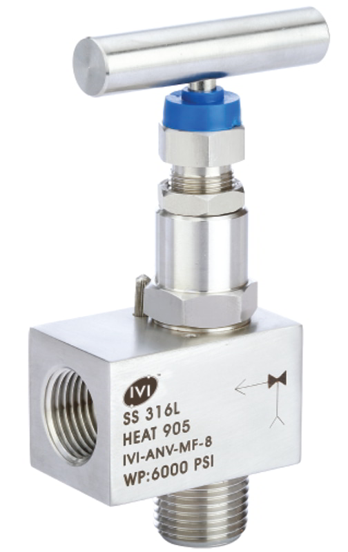
Angle Pattern Needle Valves Male x Female are designed to control the flow of liquids or gases in a piping system. The angle pattern allows the flow to change direction by 90 degrees, reducing piping complexity and minimizing pressure drop.
The male x female configuration enables easy connection to different pipe types and sizes, providing flexibility for installation in various system layouts. These valves are suitable for high-pressure applications, ensuring reliable and leak-free operation.
In oil and gas operations, they are used for controlling flow to instruments, transmitters, or equipment where space is limited and accurate flow control is needed. Metal-to-metal seals and durable stems ensure long-term performance under demanding conditions.
View Details
Surface Controlled Annular Vent and Sleeve Valve 2 inch
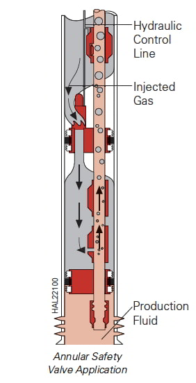
An annular vent sleeve valve communicates between the casing annulus and producing formation. The valve is a hydraulically operated sliding sleeve device like a surface controlled subsurface safety valve with a hydraulic piston and a power spring to maintain the valve in a normally closed position. The valve is used with a bull plug on top or as an annular safety valve by providing annular bypass while control pressure is applied. With an electrical feedthrough device, this valve functions through a single packer mandrel as an electric power cable passage and annular bypass. On a dual hydraulic packer, the valve operates by a common hydraulic control line that sets the packer and operates the tubing-retrievable safety valve. Hydraulic pressure from the control line shifts the valve open to create a flow path across the packer in the annulus. Spring force closes the valve upon loss of control-line pressure to the piston. If the valve becomes inoperable or closed, an emergency shear feature allows fluid to be pumped into the producing formation from the annulus. Applications » Gas lift and electric submersible pump situations Features » Accurate fluid level shot during pumping because of large ported area through the vent sleeve » Maximum gas vent flow area allows increased gas flow rates and lower circulating pressures » Valve will shut off flow from either direction — production or injection *description excerpted from manufacturers catalogue. View Details
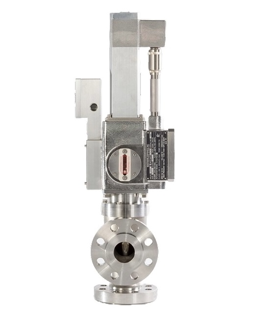
The 2″ Gas Metering Valve is designed to precisely control the flow of gas fuel in aero-derivative gas turbines, including the LM2500. By adjusting fuel delivery based on operating conditions, it maintains the optimal fuel-to-air ratio essential for safe, efficient, and reliable turbine operation.
Fuel metering valves act as the throttle control for gas turbines. Since turbines generate power by burning fuel mixed with compressed air, accurate regulation of this mixture directly impacts power output, efficiency, and emissions such as nitrogen oxides (NOx) and carbon monoxide (CO).
This valve delivers exceptional accuracy within ±1% of the flow point, ensuring consistent fuel delivery and optimal combustion. It is built to perform reliably in demanding environments and meets safety standards including ATEX, PED, and UL, certifying it for use in hazardous and extreme conditions.
The fuel metering valve is a two-inch right-angle style valve commonly used on aero-derivative turbines. It integrates easily into existing systems without requiring hydraulic or electrical changes. With millions of hours of proven field performance, it offers dependable, precise fuel control that enhances turbine efficiency and reduces fuel consumption.
View Details
Fuel Nozzle for LM2500 Gas Turbine
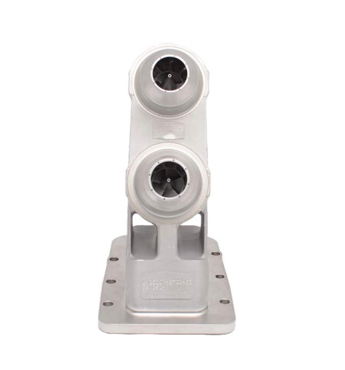
The 2-cup Fuel Nozzle is a precision-engineered component used in gas turbines, specifically in the oil and gas industry. Its primary function is to inject liquid fuel into the combustion chamber in a fine, atomized spray, allowing for optimal mixing with air and efficient ignition. This ensures stable combustion, better fuel efficiency, and reduced emissions—key performance factors in industrial turbine applications.
The “2-cup” design refers to the nozzle’s dual flow passages, which help balance fuel distribution across the combustion zone. This promotes more uniform flame stability and lowers the risk of hot spots that can cause thermal stress to the turbine hardware. The nozzle is typically used on “base” engines and is suited for continuous-duty operations.
The L47197P05 variant is known for its compatibility with LM2500 turbine configurations and is built to endure harsh operating environments. It features durable materials and a design that withstands high temperatures and pressures commonly found in oil and gas turbine systems.
View Details
FXE 2-7/8 inch Wireline Retrievable Surface Controlled Subsurface Safety Valve
The FXE wireline-retrievable flapper valve, which is normally closed, is held open by hydraulic control pressure from the surface. The valve operates on a hydraulic piston principle. To open, hydraulic pressure slightly higher than the well pressure is applied to move the piston downward. This pressure unseats the secondary seat, allowing pressure to enter through equalizing ports. Then, as additional hydraulic pressure is applied to the piston, it continues downward movement, pushing the flapper open. The flapper hinge assembly is designed such that the force on the piston is not applied directly on the hinge pin. Upon loss of hydraulic pressure in the control line, the valve’s large spring serves to lift the hydrostatic head of the control fluid. The flapper spring is designed to close the valve when the piston moves up past the flapper. Opening Prong Nose Seal The FXE valve uses the valve housing as the downstop for the opening prong. This metal-to-metal (MTM) interface is designed to prevent flow from passing between the valve housing and the opening prong. The MTM interface isolates the flapper and seat from fluid flow while the valve is open. This design creates an MTM interface with the full force exerted by the hydraulic piston, minus the spring compression force, holding the two metal faces in contact. Radius of Curvature at Flow Entrance Halliburton conducted a study with various curvatures on the entrance to the valve. The study tested abrasive fluids flowing through different test subs and examined the resulting wear patterns. As a result, an optimum radius of curvature was determined and implemented on the valve housings of all wireline-retrievable safety valves. Applications » General production completions Features » Equalizing-type flapper closure » Solid construction flapper made from bar stock » Spherical radius seat on flapper improves seal reliability » Sealing and seating surfaces are out of the well production flow path when valve is in the open position *information referenced from supplier catalog. View Details
Ambient Storm Choke Valve 4 1/2 inch
Storm Choke® H safety valves are ambient-type, wireline retrievable valves that are normally closed and precharged with a set dome pressure. When the well flowing pressure drops below the predetermined dome-pressure charge, as a result of a rupture in the flowline or surface equipment, the dome pressure and valve spring are designed to close the valve, shutting in the well. The H valve is used in wells producing large volumes of abrasive fluids. Its large bore is not restricted by a flow bean. The valve is designed to resist pressure surges. A metal-to-metal (MTM) ball and seat is used as the primary closure mechanism. The H valve is ideal for protecting wells with declining bottomhole pressure because this valve is tubing pressure sensitive instead of velocity sensitive. To reopen, the valve pressure must be fully equalized either by applying pressure in the tubing from the surface or by running a prong to allow equalization from below. The valve will reopen when the tubing pressure acting on the internal piston area overcomes the dome charge. Applications » Wells producing large volumes of abrasive fluids » Wells with declining bottomhole pressure » Wells with no provisions for surface-controlled valves Features » Large bore not restricted by a flow bean » MTM ball and seat » Designed to resist pressure surges *description excerpted from manufacturers catalogue. View Details
Tube Fittings Male Connectors are precision parts used to connect tubing directly to a threaded port in oil and gas systems. One side of the connector is designed for tubing, while the other side has an ISO tapered male thread that screws into valves, manifolds, pumps, or other equipment.
These connectors are made for high-pressure applications, with working pressure ratings up to 6000 PSI. The tapered thread design creates a tight, reliable seal that prevents leaks of gas or liquid, even under vibration, temperature changes, or fluctuating pressures.
They are commonly used in drilling rigs, wellhead equipment, hydraulic control lines, instrumentation systems, and process piping. Available sizes include 1/8”, 5/16”, 3/8”, and 1/2”, making them suitable for a wide range of tubing diameters.
By ensuring a strong, leak-free connection, Tube Fittings Male Connectors improve safety, reduce downtime, and support efficient operation in demanding oil and gas environments.
View Details
Gauge Root Valve – Female x Female – 1/4” NPT – 6000 PSI – ASME B16.34 / ISO 9001 / PED / ATEX
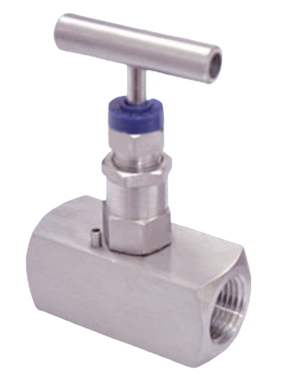
The Gauge Root Valve Female x Female 1/4” NPT is a small but essential valve used to protect and control pressure instruments, like gauges and transmitters, in fluid or gas systems. Its female x female connection allows it to connect directly to two male-threaded fittings, making installation simple and reducing the risk of leaks.
This valve can handle pressures up to 6000 PSI and operates safely across a wide temperature range. The internal stem is designed with a back seat and the packing is placed below the threads, keeping the threads protected from the process media. A self-centering, non-rotating tip ensures a tight seal every time, preventing leaks.
It also features a removable “T” handle for easy turning with low effort, smooth rolled threads for long-lasting use, and a dust cap to prevent dirt or debris from entering the valve. Each valve is factory tested with nitrogen at 1000 PSI to ensure it seals correctly and operates reliably. This type of valve is ideal for isolating and protecting pressure instruments in chemical, oil and gas, and industrial processes.
View Details
High-Performance 7" Surface-Controlled Subsurface Safety Valve
Available sizes: 2 3/8”, 2 7/8”, 3 1/2”, 4”, 4 1/2”, 5”, 5 1/2'” and 7”.
The 7-inch Subsurface Controlled Surface Safety Valve (SCSSSV) is a critical safety device designed to automatically shut in a well if uncontrolled flow occurs due to equipment failure or damage. It is installed in the upper part of the well to quickly isolate the producing zone and prevent uncontrolled release of fluids, ensuring well control in emergency situations.
This valve uses a flapper mechanism and is surface-controlled, meaning it can be operated from the surface. It features a self-equalizing design that reduces pressure differences across the valve during opening and closing, which improves reliability and extends valve life. The sealing surfaces are located outside the flow path when the valve is open, reducing wear and protecting key components from erosion.
Because the valve is wireline retrievable, it can be serviced or repaired without pulling the entire tubing string, minimizing downtime and intervention costs. It fits 7-inch tubing and is available with landing nipple seal bores of 5.750", 5.875", or 5.963". It can handle working pressures up to 10,000 psi and offers valve internal diameters of 3.38" and 3.50", allowing operators to balance safety and flow requirements effectively.
View Details
Water Injection Safety Valve Type MC 5-1/2 inch
MC (flapper-type) injection valves are used in injection wells to automatically shut-in the tubing string when injection stops or flow reverses. MC injection valves are spring-loaded, wireline-retrievable valves with large bores. The MC injection valves also feature sealing areas that are out of the direct flow path. These valves are designed to be held open by injection pressure for fluid passage. If injection flow becomes static or reverses for any reason, the spring and/or reverse flow causes the valves to close. These valves are designed to remain closed until pressure differential across the valves is equalized and injection is resumed. Applications » Injection wells Features » MC valves have sealing areas that are out of the direct flow path *information sourced from manufacturer View Details
TIG AC/DC 281 Pulse Welding Machine
Introducing the TIG AC/DC 281 Pulse: Precision Welding at its Finest When it comes to precision welding, the TIG AC/DC 281 Pulse from Canaweld stands head and shoulders above the rest. As an industrial, heavy-duty, and powerful welding machine, it has been designed to deliver exceptional results, making it the ideal choice for all your welding needs. Precision Pulse Welding - Unmatched Quality The TIG AC/DC 281 Pulse is equipped with professional pulse features and an HF start that allows welders to achieve high-quality TIG welds even on the thinnest materials without any distortion. Its inverter-based arc welding power source with advanced waveforms and pulse controls sets a new standard for welding excellence in industrial workshops. Advanced 5-inch Color Display - Simplified Control Navigating your welding experience is effortless with the TIG AC/DC 281 Pulse's 5-inch LCD screen. Whether you're an experienced welder or a novice, this display empowers you to quickly and accurately set and select the right parameters, reducing setup time and increasing your actual welding productivity. All the features can be easily customized and saved in the available memory settings, ensuring consistency and efficiency in every project. Powerful Performance and Versatility With the TIG AC/DC 281 Pulse, you can tackle a wide range of welding tasks with ease: • Capability to TIG weld aluminum and steel workpieces up to 3/8 inch (9.5 mm) in thickness, delivering a maximum output of 280 amps for demanding applications. • AC waveforms, including progressive square wave, sine wave, and triangular wave, provide precise control for different materials and welding needs. • Up to 10 memory locations to store your most important weld parameters, giving you quick access to frequently used settings. • Adjustable soft welding start and powerful start options, ensuring perfect arc initiation for both thin and thicker materials. • Adjustable balance settings for aluminum welding, allowing you to control cleaning and penetration sequences effectively. Built Tough for Challenging Environments The TIG AC/DC 281 Pulse is engineered to withstand the toughest conditions, thanks to its rigorous testing in (104°F/40°C). Its durable and efficient design ensures you can rely on it for flawless performance, no matter where your welding projects take you. Efficiency Meets Innovation The TIG AC/DC 281 Pulse offers innovation at its core: • High-frequency (HF) start for perfect arc initiation and stability, minimizing downtime and maximizing productivity. • Digital control of all welding parameters, giving you complete control over the welding process. • Amperage control accessible by foot pedal, providing precise control over welding intensity. • Pulse TIG welding for better arc control and minimized workpiece distortion, perfect for achieving immaculate welds. • The ability to use up to 165 feet (50 meters) leads without any power loss, ensuring flexibility and mobility in your workspace. • Digital adjustment of pre-flow, initial amperage, welding amperage, initial slope, pulse parameters, final slope, and post-flow, enhancing precision and efficiency. Unwavering Commitment to Quality With Canaweld's comprehensive 3-year warranty, you can weld with peace of mind, knowing that your TIG AC/DC 281 Pulse is backed by our commitment to quality and customer satisfaction. Innovative Wind Tunnel for Cooling Efficiency The TIG AC/DC 281 Pulse incorporates an innovative wind tunnel for cooling efficiency, ensuring consistent performance even during long welding sessions. Experience Precision Welding with Canaweld Take your welding to the next level with the TIG AC/DC 281 Pulse from Canaweld. Experience precision welding at its finest and elevate your projects with unparalleled performance and control. Choose Canaweld and let the TIG AC/DC 281 Pulse redefine your welding experience. Achieve perfection with Canaweld! View Details
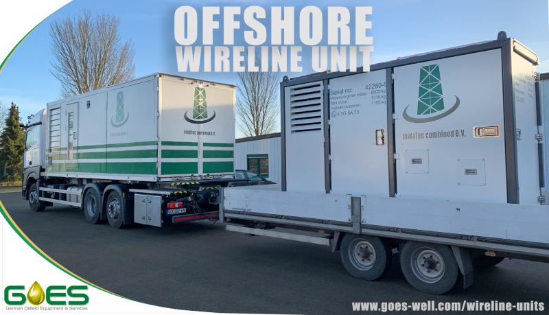
Offshore Electric Line Services
Navigating the Depths: InWaTec Combined's Advanced Offshore E-Line Services In the challenging and complex world of offshore operations, precise and dependable wellbore data transmission is not just beneficial—it's crucial. At InWaTec Combined, our Offshore Electric Line (E-Line) services are the cornerstone of our well diagnostics and intervention solutions, designed to conquer the unique demands of the offshore environment. An E-Line, in its simplest form, is a robust electric cable. Yet, when deployed by InWaTec Combined, it becomes an integral part of offshore operations, a sophisticated tool that delves into the wellbore's mysterious realms. Our E-Line services excel in transmitting real-time data about the wellbore's conditions back to our offshore experts, ensuring that critical decisions are made with the utmost information at hand. Our E-Line's forte lies in its versatility and utility in conducting a plethora of logging activities essential for evaluating the well's integrity, formation properties, and hydrocarbon potential. These activities enable a comprehensive understanding of the well, providing insights necessary for optimizing production and ensuring the safety of offshore operations. The offshore environment poses unique challenges with its unpredictable nature and the sheer scale of operations. InWaTec Combined's E-Line services are designed to be resilient and adaptable, capable of withstanding the high pressures and corrosive elements found in the deep sea. Our commitment to innovation means that our E-Line technology is continuously evolving, pushing the boundaries of what is possible in offshore data gathering. By choosing InWaTec Combined's Offshore E-Line services, our clients receive more than just data—they gain a strategic advantage. With our advanced technology and expert analysis, we provide the insights necessary to maximize well performance, extend the life of offshore assets, and enhance the overall safety and efficiency of offshore operations. In an industry where the margin for error is slim and the consequences significant, InWaTec Combined stands as a beacon of reliability and excellence. Our Offshore E-Line services are not just a component of your operations—they are a pivotal part of your success story, deep beneath the waves. View Details




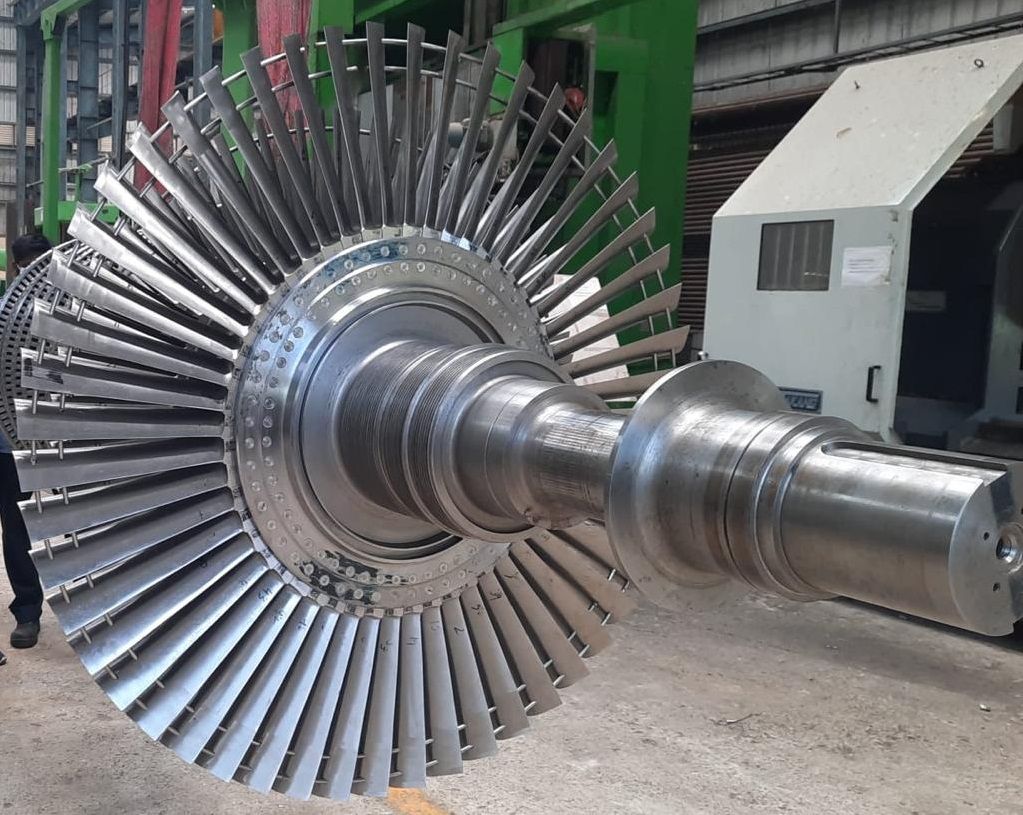
LM2500+G4 SAC 50Hz CC 1x1 Gas Turbine
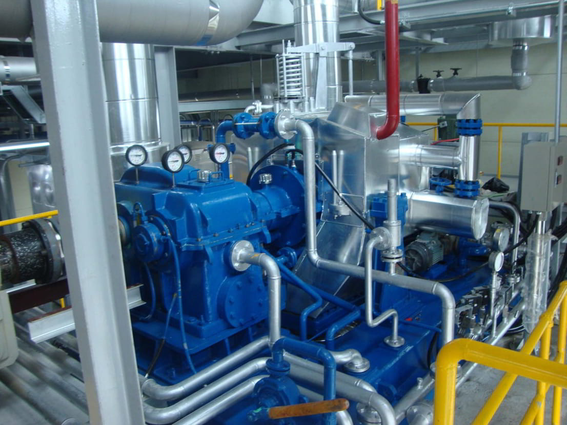
The LM2500+G4 SAC 50Hz Combined Cycle 1x1 is a gas turbine system that combines a gas turbine with a steam turbine to improve overall power generation efficiency. This configuration captures waste heat from the gas turbine exhaust and uses it to produce steam, which then drives the steam turbine, generating additional electricity. This approach helps maximize power output while making better use of fuel energy.
Building on the LM2500+ design, the LM2500+G4 increases power capability by about 10% without reducing the lifespan of critical hot section components. This is achieved by increasing airflow, enhancing materials, and improving internal cooling. Despite these upgrades, the core compressor and turbine stages, as well as most airfoil and combustor designs, remain consistent with the LM2500 model.
The LM2500+G4 features a 17-stage high-pressure compressor that raises the engine’s pressure ratio and airflow, boosting the total power output of the gas turbine to over 31 MW. It uses a Single Annular Combustor (SAC) equipped with water injection to help control emissions while maintaining stable combustion. The SAC’s simple, proven design provides uniform flame temperature and reliable operation.
This balanced system is common in industrial and energy applications where efficiency and power output must be optimized, especially under varying ambient conditions. The combined cycle setup offers a reliable and efficient solution for electricity generation in demanding environments.
View Details
Valve and Prong Type Equalizing Sub-Assembly
Maximize Downhole Functionality with HOCA Oil Tools' Valve and Prong Type Equalizing Sub Assemblies In the complex world of downhole operations, precision and reliability are paramount for ensuring the safety and efficiency of well interventions. At HOCA Oil Tools, we understand the critical nature of these operations and respond with our top-tier Valve and Prong Type Equalizing Sub Assemblies. These specialized tools are designed to address and overcome the unique challenges presented by downhole environments, ensuring that your operations proceed smoothly and effectively. HOCA’s Valve and Prong Type Equalizing Sub Assemblies: Tailored for Excellence Our Valve and Prong Type Equalizing Sub Assemblies are engineered to facilitate the critical process of pressure equalization in downhole operations, particularly during the installation or retrieval of downhole equipment. These assemblies are essential for safely managing pressure differentials, preventing equipment damage, and ensuring the safety of the wellbore and personnel. Available in a variety of configurations to meet different well conditions and requirements, our equalizing subs are constructed with precision and durability in mind. Experience the HOCA Oil Tools Difference Choosing HOCA Oil Tools’ Valve and Prong Type Equalizing Sub Assemblies means opting for a product backed by expertise, innovation, and commitment to quality. We pride ourselves on providing solutions that not only meet but exceed the rigorous demands of the oil and gas industry. Whether you are facing standard operational tasks or unique downhole challenges, our equalizing subs provide the performance and reliability essential for success. Incorporating our Valve and Prong Type Equalizing Sub Assemblies into your downhole toolkit is a step towards enhanced operational efficiency, safety, and success. With HOCA Oil Tools, you gain more than just equipment; you gain a partner dedicated to supporting your downhole challenges with state-of-the-art solutions and comprehensive service. Opt for HOCA Oil Tools for your downhole needs and take the first step towards optimized operations. Partner with us and leverage the power of advanced downhole solutions designed to enhance your oilfield success. With HOCA Oil Tools, empower your downhole operations with tools that set new standards in efficiency, safety, and performance in the oil and gas industry. View Details
5" Mech-2 Double Grip Mechanical Set Packer for 11.5-15 PPF Casing
Ballycatter Mech-2 Double Grip Mechanical Packer
Available sizes: 5”, 5 1/2”, 6 5/8”, 7”, 9 5/8”, and 10 3/4”
The Ballycatter Mech-2 is a retrievable, compression-set double-grip mechanical packer designed for applications where pressure differentials from below are anticipated, such as combined stimulation and production operations. Featuring opposing slips above and below the packing element, the Mech-2 ensures secure bi-directional anchoring within the casing under varying well conditions.
The tool incorporates a built-in hydraulic hold-down system located beneath the face-seal bypass valve, enabling it to resist upward forces during stimulation treatments. A unique “Differential Lock” mechanism utilizes pressure from below the packer to actuate a balance sleeve, generating additional downward force that maintains bypass valve integrity and ensures a reliable seal.
The Mech-2 is mechanically set using a long-stroke mandrel and a J-slot mechanism. Once positioned, right-hand rotation and applied set-down weight close the bypass valve, engage both slip sets, and compress the sealing elements. The formation below the packer is then fully isolated and accessible only through the tubing. To retrieve, the tubing is raised the full packer length, automatically re-engaging the J-slot and reopening the bypass for pressure equalization and circulation.
With its dual-grip design, hydraulic hold-down, and controlled setting and release process, the Mech-2 offers a robust and dependable solution for demanding applications requiring secure annular isolation and enhanced downhole stability.
View Details